
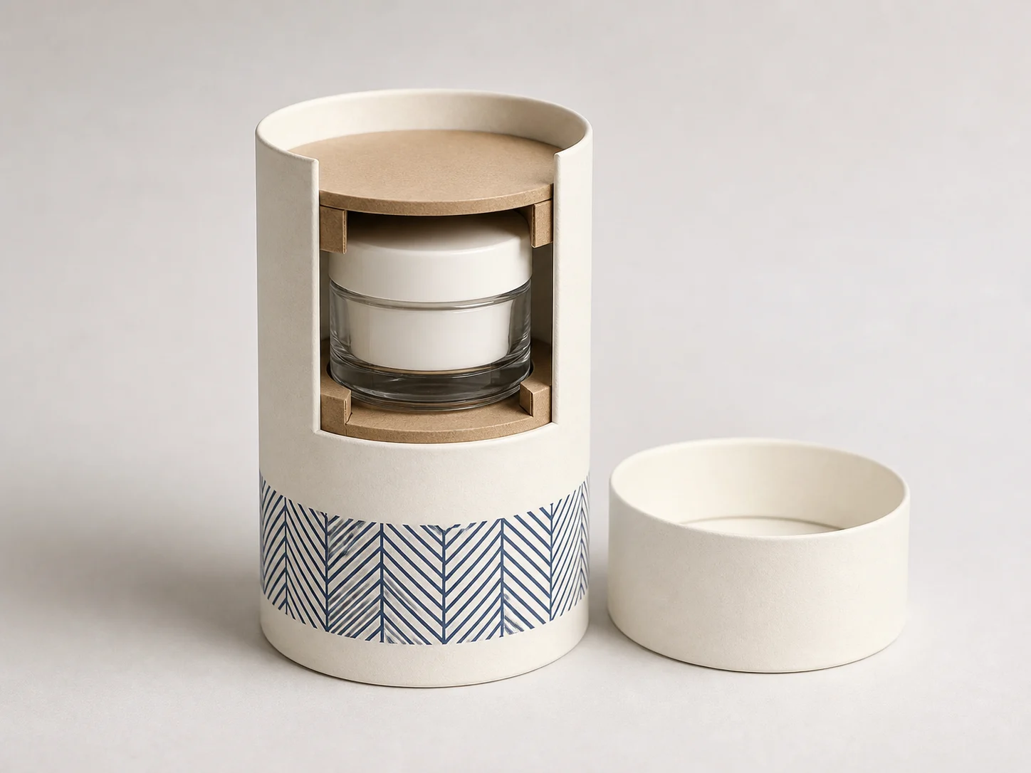
Start with the product envelope, not the tube diameter
A finished item can have a cap, label, shoulder or accessory that changes its maximum envelope. Share those points first. Then identify usable side, top and base clearance so the support layout is based on the product rather than an assumed tube size.
Check the assembled clearance budget
Measure usable internal height with the intended closure seated. Subtract the finished product height and the space occupied by the proposed top and base supports. The remainder is the axial clearance to review; a nominal outside tube height cannot answer this question. Check the largest product envelope against the support opening separately, including labels, caps and seams.
Do not apply one universal clearance number. Ask the supplier to state which dimensions are controlled, how the sample will be measured, and whether an agreed contact point is on the body, base or closure. A support pressing on an unsuitable cap, pump or decorated surface may create a different problem from free movement.
Choose the contact arrangement before the artwork
A solid end pad, an open-center support and folded stand-offs create different contact arrangements. Compare them using the actual item and the intended loading sequence. Record whether the item can be inserted and removed without disturbing the supports, whether the lid closes as intended, and whether the agreed contact areas remain acceptable after the required checks. These are sample-review questions, not proof that a pictured concept has passed testing.
Six fields for a comparable end-support RFQ
Product envelope
Record the widest finished diameter, full height, weight, orientation and any cap or accessory that changes the envelope.
Radial location
Define how the product should sit around the tube centerline, including permitted side clearance and contact points.
Axial location
Define top and base clearance rather than relying on one nominal tube height.
Separate supports
Describe whether the top, base or both ends use die-cut paperboard supports, their cavity geometry and intended contact areas.
Tube presentation
State wrap artwork, seam location, print method and finish direction separately from the support system.
Sampling
Agree measurable fit, opening and visual checks before treating the structure as approved.
Keep three decisions separate
- The cylindrical tube body defines the package envelope and presentation direction.
- Separate paperboard end supports locate the packed item at selected contact points.
- Production approval depends on a project-specific sample; this concept does not prove retention, transport testing, food contact or compliance.
Request a support-layout review
Send product dimensions, weight, desired orientation, support locations, artwork status, quantity and destination market. MUGE PACKAGING can review the proposed structure before sampling.